Replacing a Burnt Resistor on a Circuit Board
Resistors are fundamental components in electronic circuits, and their failure can disrupt the operation of a device. When a resistor burns out, it often exhibits visible signs such as discoloration, charring, or cracking, and its resistance may drift from the specified value. Identifying a burnt resistor is the first step in the replacement process, followed by testing to confirm the fault. This article outlines a systematic approach to diagnosing and replacing a burnt resistor on a circuit board, emphasizing careful technique and safety.
The process involves several stages: visual inspection, resistance measurement, desoldering the faulty component, preparing the replacement, and soldering it into place. Each step requires attention to detail to avoid damaging the circuit board or surrounding components. While the procedure is straightforward, it demands patience and a methodical mindset. By following the guidelines here, you can improve your chances of a successful repair.
Identifying a Burnt Resistor
Visual inspection is the primary method for detecting a burnt resistor. Look for signs of overheating, such as a brown or blackened body, cracked casing, or a charred smell. Sometimes, the discoloration may appear as a dark band or a blister on the resistor’s surface. In severe cases, the resistor may be completely destroyed, with its internal elements exposed. It’s important to compare the suspect resistor with others on the board to spot anomalies.
However, not all burnt resistors show obvious physical damage. Some may fail without visible signs, especially if the overheating was brief or if the resistor is encapsulated. In such cases, testing with a multimeter becomes necessary. Additionally, a burnt resistor may cause adjacent components to overheat or fail, so inspect the surrounding area for collateral damage. If you notice a burnt smell but no visible damage, consider that the resistor might still be faulty.
When inspecting, use a magnifying glass or a microscope if available to examine the resistor closely. Check for hairline cracks or subtle color changes that might indicate stress. Also, look for any signs of arcing or soot on the board, which can indicate a short circuit. Remember that a discolored resistor is not always defective; some resistors naturally darken with age, but if the discoloration is uneven or accompanied by other symptoms, further testing is warranted.
Testing Resistance
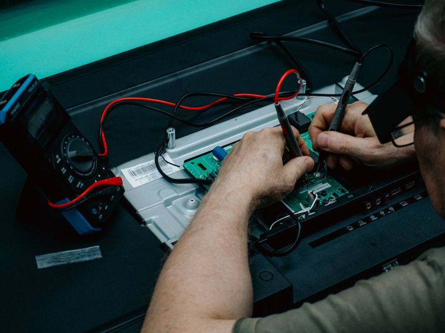
To confirm whether a resistor is faulty, measure its resistance with a digital multimeter. Before testing, ensure the circuit board is disconnected from any power source and that any capacitors are discharged to avoid electrical shock or damage to the meter. Set the multimeter to the appropriate resistance range, or use the auto-ranging feature if available. If the resistor is still soldered in the circuit, the measurement may be affected by parallel paths; for accurate results, it’s best to desolder one leg of the resistor or remove it entirely.
Compare the measured resistance to the nominal value indicated by the color code or printed on the resistor. A resistor is typically considered faulty if its resistance is more than 10% above or below the nominal value, though this tolerance can vary depending on the circuit’s requirements. If the multimeter displays an open circuit (infinite resistance) or zero resistance, the resistor is definitely defective. In some cases, the resistance may fluctuate, indicating an intermittent fault; such resistors should also be replaced.
When testing, keep in mind that temperature can affect resistance. If the resistor is warm, allow it to cool to room temperature before measuring. Also, ensure that your multimeter is calibrated and in good working condition. If you’re unsure about the resistor’s expected value, consult the schematic or service manual for the device. Without a schematic, you can sometimes infer the value from similar circuits or by using online resources, but this approach requires caution. Testing is a critical step that prevents unnecessary replacement of good components.
Desoldering the Faulty Resistor
Once you’ve confirmed that a resistor is faulty, the next step is to remove it from the circuit board. Desoldering requires a soldering iron with a fine tip, solder wick or a desoldering pump, and flux. Begin by applying a small amount of fresh solder to the existing joints; this helps improve heat transfer and makes the old solder easier to remove. Then, heat the joint with the soldering iron and use the solder wick or pump to remove the molten solder. Be careful not to apply excessive heat, as this can damage the board’s pads or traces.
If the resistor is held by bent leads, straighten them gently with tweezers while heating the joints. For through-hole resistors, you may need to alternate heating between the two leads until both are free. For surface-mount resistors, use a hot air rework station or a soldering iron with a specialized tip to heat both ends simultaneously, then lift the component with tweezers. Always handle the board with care to avoid cracking or lifting pads.
After removing the resistor, clean the area with isopropyl alcohol and a brush to remove any flux residue. Inspect the pads and traces for damage; if a pad is lifted, you may need to repair it with a jumper wire. Also, check for any solder bridges that might have formed during desoldering. Proper cleaning ensures good adhesion for the new component and prevents corrosion. If you’re using FixCircuit’s repair services, they emphasize the importance of thorough cleaning and inspection after desoldering.
Selecting and Preparing the Replacement
Choose a replacement resistor with the same resistance value and power rating as the original. The power rating, measured in watts, indicates how much heat the resistor can dissipate; using a lower-rated resistor may cause it to overheat and fail prematurely. If the original resistor’s power rating is not visible, estimate it based on the circuit’s voltage and current, or consult the schematic. Tolerance is also important: common tolerances are ±5% and ±1%, but for precision circuits, a tighter tolerance may be required.
Before soldering, verify the new resistor’s resistance with a multimeter to ensure it matches the required value. If you’re replacing a surface-mount resistor, ensure the package size is compatible with the board’s footprint. For through-hole resistors, you may need to trim the leads to the appropriate length and form them to fit the holes. If the resistor is part of a critical circuit, consider using a resistor with a higher power rating for improved durability, but ensure it fits physically.
It’s also wise to check for any other components that might have been affected by the original resistor’s failure. For instance, if the resistor burned due to an overcurrent condition, the cause might still be present, and the new resistor could also fail. Investigate the root cause, such as a shorted capacitor or a faulty transistor, before proceeding. FixCircuit recommends a comprehensive diagnosis to prevent repeat failures.
Soldering the New Resistor
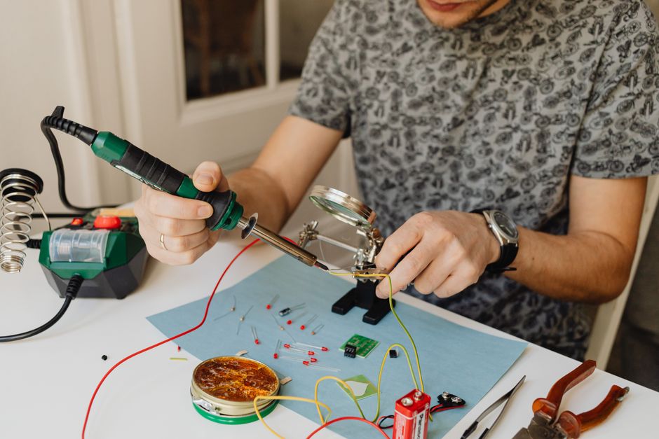
Soldering the new resistor requires a clean soldering iron tip, fresh solder, and flux. For through-hole resistors, insert the leads into the holes and bend them slightly to hold the component in place. Apply flux to the joint, then heat the pad and lead with the soldering iron for a second or two, and feed solder into the joint. Aim for a shiny, concave solder fillet. Avoid using too much solder, as it can create bridges. After soldering, trim the excess leads.
For surface-mount resistors, position the component with tweezers, ensuring it is aligned with the pads. Hold it in place and solder one end first, then solder the other end. Use a fine tip and minimal solder to avoid bridging. If you’re not experienced with surface-mount soldering, practice on a scrap board first. After soldering, inspect the joints under magnification for cold solder joints, which appear dull and irregular. Reheat any questionable joints.
Once soldered, clean the area again to remove flux. Then, perform a visual inspection and a resistance check to ensure the resistor is properly connected. If the circuit board has other components nearby, ensure they are not disturbed. Finally, before powering up the device, double-check all connections and look for any stray solder balls. Testing the device after repair is essential, but be prepared for the possibility that other issues may exist. Remember that repairing a circuit board carries inherent risks, and if you’re unsure, seek professional assistance.